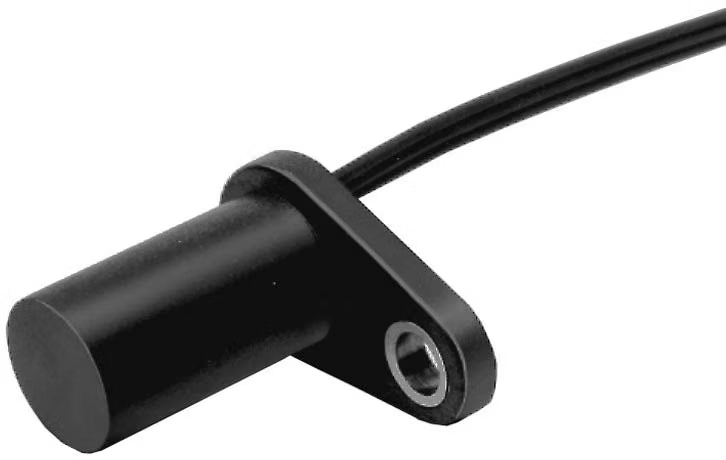
Basic Info.
Model NO.
GVS-H-03
Material
Stainless Steel, Metal
Production Process
Integration
Output
Analog Sensor
Type
Hall Wheel Speed Sensor
Sensor Type
Hall Sensor
Transport Package
Carton
Trademark
Yuanben
Origin
Shanghai
Production Capacity
200, 000PCS/Year
Product Description
GVS-001 Hall-Effect Gear Speed Sensor
Description
GVS Series Tooth Sensors use a magnetically biased Hall effect integrated circuit to accurately sense movement of ferrous metal targets. This specially designed I.C., with discrete capacitor and bias magnet, is sealed in a probe type package for physical protection and cost effective installation.
Output is digital, current sinking (open Collector). Reverse polarity protection is standard. If power is inadvertently wired backwards, the sensor will not be damaged.
Optimum sensor performance is dependent on the following variables which must be considered in combination:
Features
Typical Applications
Automotive and Heavy Duty Vehicles:
Specifications

Target
Diameter: 4 inch. (101,6 mm)
Tooth Width: .350 inch. (8,89 mm)
Thickness: .250 inch. (6,35 mm)
Test Conditions
Air Gap: .040 to .080 inch. (1,02 to 2,03 mm)
Power Supply: 4.5 to 24 Vdc
RPM: 10 min., 3600 max.
Mounting dimension (For reference only)

Photos


Description
GVS Series Tooth Sensors use a magnetically biased Hall effect integrated circuit to accurately sense movement of ferrous metal targets. This specially designed I.C., with discrete capacitor and bias magnet, is sealed in a probe type package for physical protection and cost effective installation.
Output is digital, current sinking (open Collector). Reverse polarity protection is standard. If power is inadvertently wired backwards, the sensor will not be damaged.
Optimum sensor performance is dependent on the following variables which must be considered in combination:
- Target material, geometry, and speed
- Sensor/target gap
- Ambient temperature
- Magnetic material in close proximity
Features
- Senses ferrous metal targets
- Digital current sinking output (open collector)
- Better signal-to-noise ratio than variable reluctance sensors, excellent low speed performance, output amplitude not dependent on RPM
- Sensor electronically self-adjusts to slight variations in runout and variations in temperature, simplifying installation and maintenance
- Fast operating speed - over 100 kHz
- EMI resistant
- Reverse polarity protection and transient protection (integrated into Hall I.C.)
- Wide continuous operating temperature range
Typical Applications
Automotive and Heavy Duty Vehicles:
- Camshaft and crankshaft speed/position
- Transmission speed
- Tachometers
- Anti-skid/traction control, ABS system
- Sprocket speed
- Chain link conveyor speed and distance
- Stop motion detector
- High speed low cost proximity
- Tachometers, Counters
- Gear tooth Sensor
Specifications
- All values were measured using 1 K pull-up resistor.
- Electrical Supply Voltage 4.5 to 24 VDC
- Output Voltage (output low) 0.4 V max.
- Output Current (output high) 10 µA max. leakage into sensor
- Switching Time Rise (10 to 90%) 15 µsec. max.
- Fall (90 to 10%) 1.0 µsec. max.
- Absolute Supply Voltage (Vs) ±30 VDC continuous
- Maximum Voltage Externally Applied Ratings To Output (output high) -0.5 to +30 V
- Output Current 40 mA sinking
- Temperature RangeStorage -40 to 150°C (-40 to 302°F)
- Operating -40 to 150° C (-40to302°F)
- Switching Operate Point 3.7±1.25° (3,28±1,13 mm)
- Characteristics Release Point 4.7±2.50° (4,16±2,21 mm)
- Differential Travel 8.4±3.70° (7,45±3,34 mm)
Target refrence and conditions
The Target Guidelines table provides basic parameters when an application is not restricted to a specific target.
Any target wheel that exceeds the follow-ing minimum specifications can be sensed over the entire temperature range of -40° to 150°C with any sensing gap up to 2,0mm. This data is based on a 102 mm diameter wheel, rotating 10 to 3600 RPM.
Reference Target Dimensions

Characteristics will vary due to target size, geometry, location, and material. Sensor specifications were derived using a cold-rolled steel reference target. See table, for reference target configuration and evaluation conditions. The Target Guidelines table provides basic parameters when an application is not restricted to a specific target.
Any target wheel that exceeds the follow-ing minimum specifications can be sensed over the entire temperature range of -40° to 150°C with any sensing gap up to 2,0mm. This data is based on a 102 mm diameter wheel, rotating 10 to 3600 RPM.
Reference Target Dimensions
| Tooth Height: | .200 in. (5,06 mm) min. |
| Tooth Width: | .100 in. (2,54 mm) min. |
| Tooth Spacing: | .400 in. (10,16 mm) min. |
| Target Thickness: | .250 in. (6,35 mm) |
Target
Diameter: 4 inch. (101,6 mm)
Tooth Width: .350 inch. (8,89 mm)
Thickness: .250 inch. (6,35 mm)
Test Conditions
Air Gap: .040 to .080 inch. (1,02 to 2,03 mm)
Power Supply: 4.5 to 24 Vdc
RPM: 10 min., 3600 max.
Mounting dimension (For reference only)
Photos
